Summary
Most of the scientific activities can only be carried out with the usage of winches. Therefore the winches are among the most important devices onboard. The winch concept aims to redundancy and flexibility. Smooth operation is overseen by the ship's engineers.
|
|
|
Contacts
| Name | Institution | Role |
|---|---|---|
| Reederei Briese | Reederei Briese | Engineer In Charge |
Components
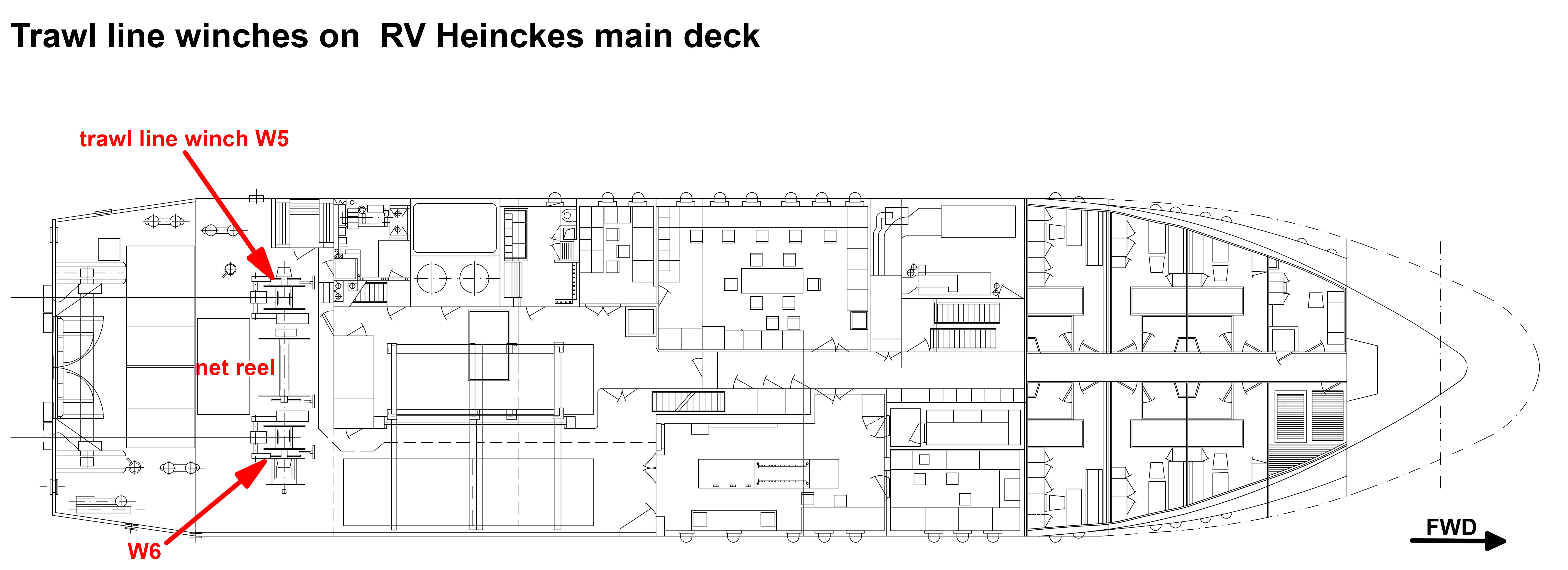
Following winches are used onboard:
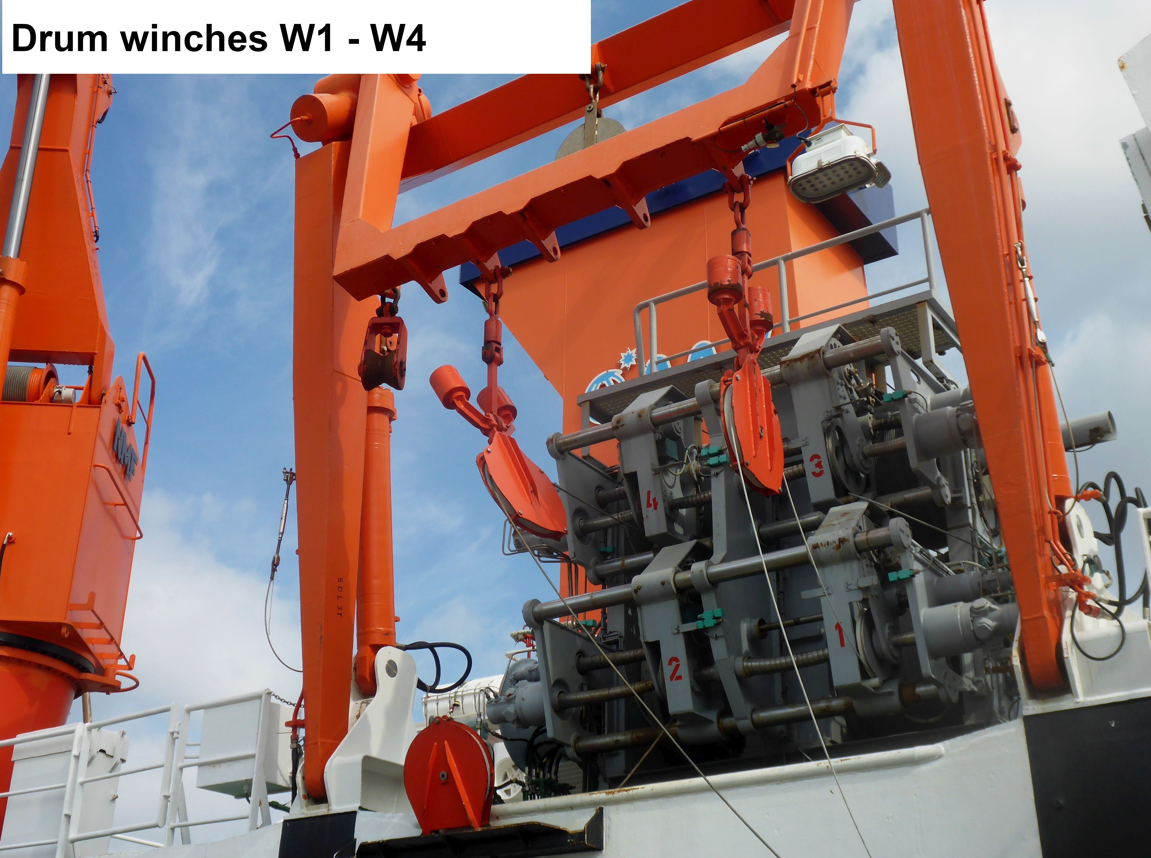
W1-W4 | 4-drum winches |
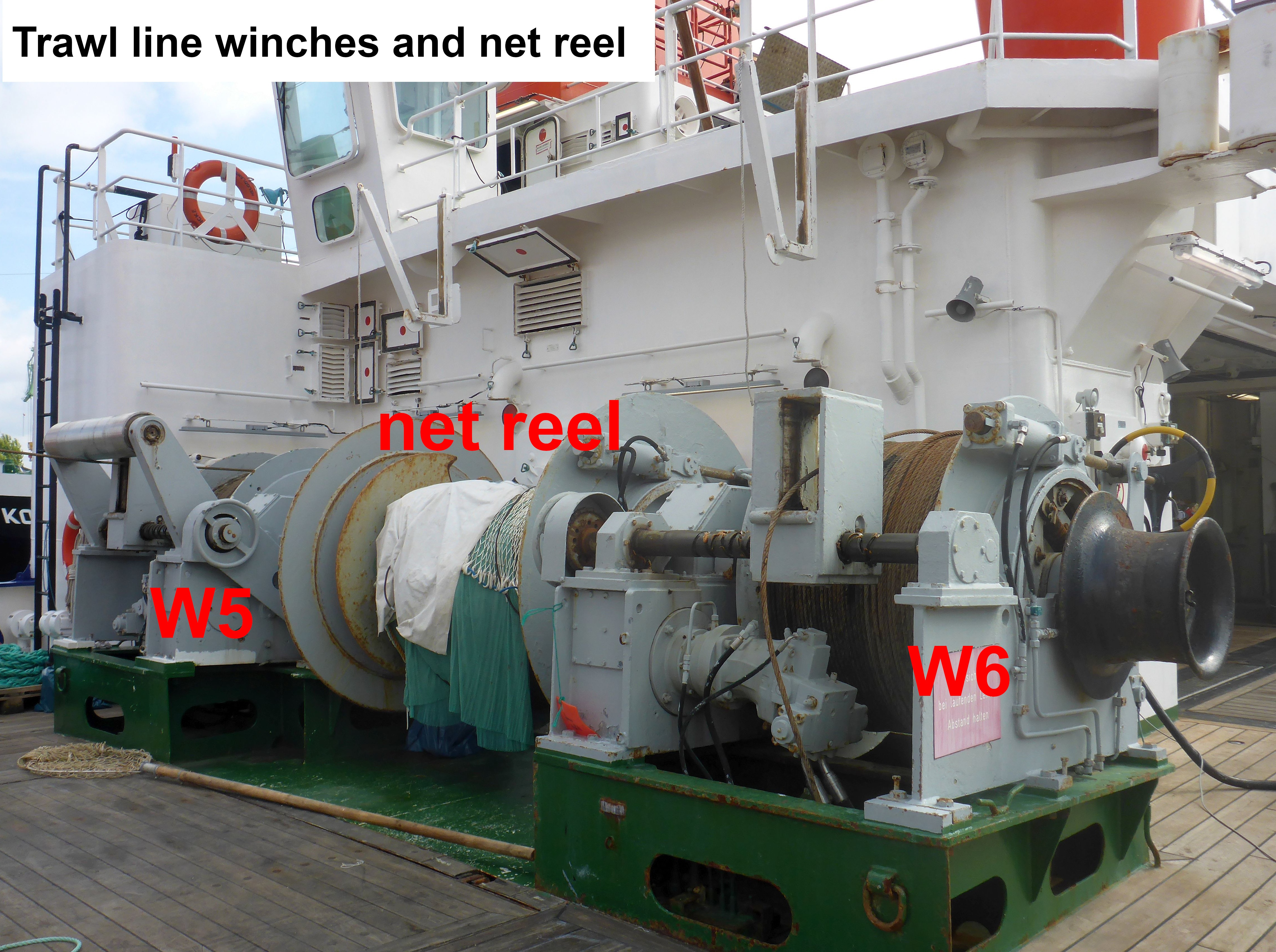
W5 | trawl line winch starboard |
W6 | trawl line winch portside (net reel is installed between W5 and W6) |
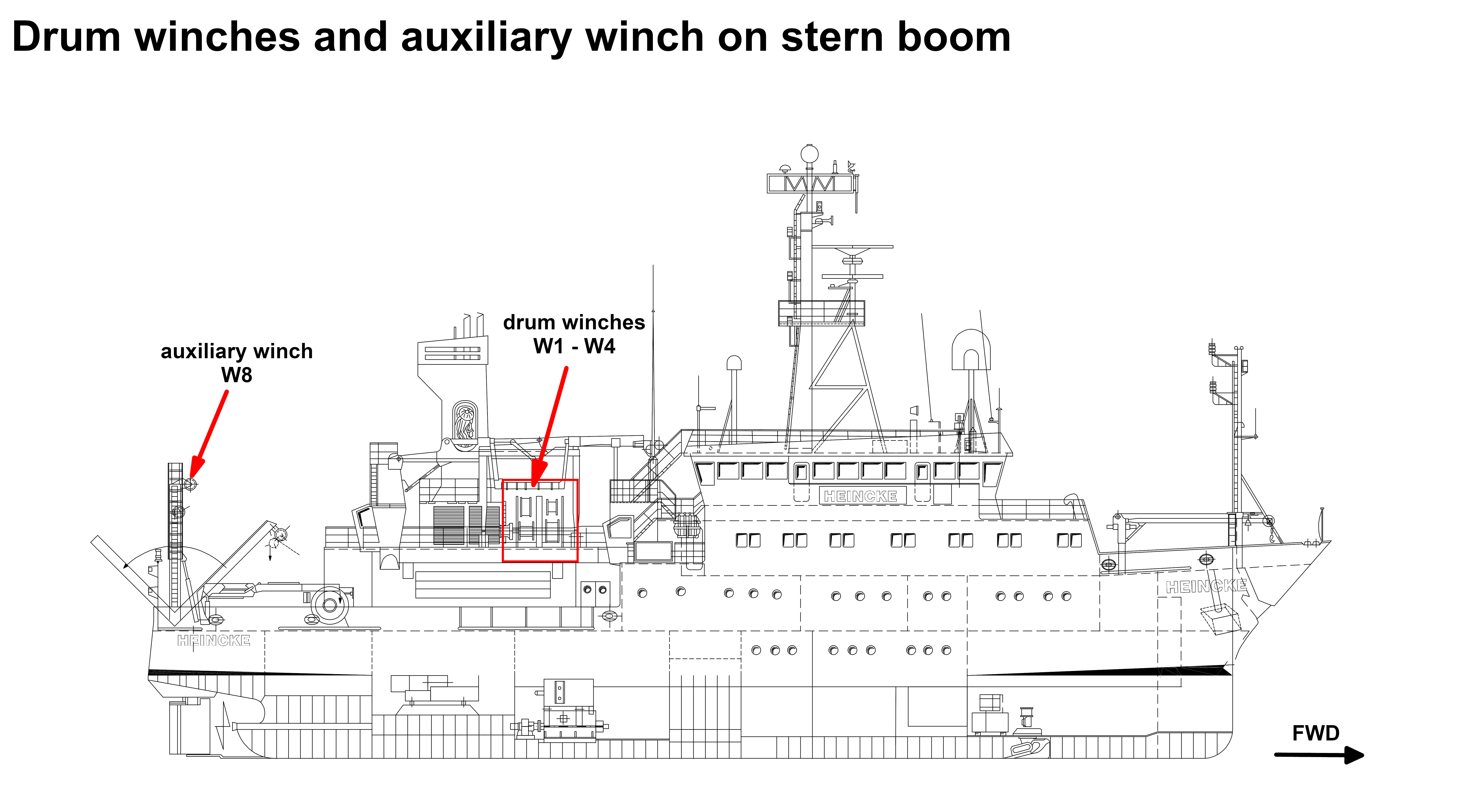
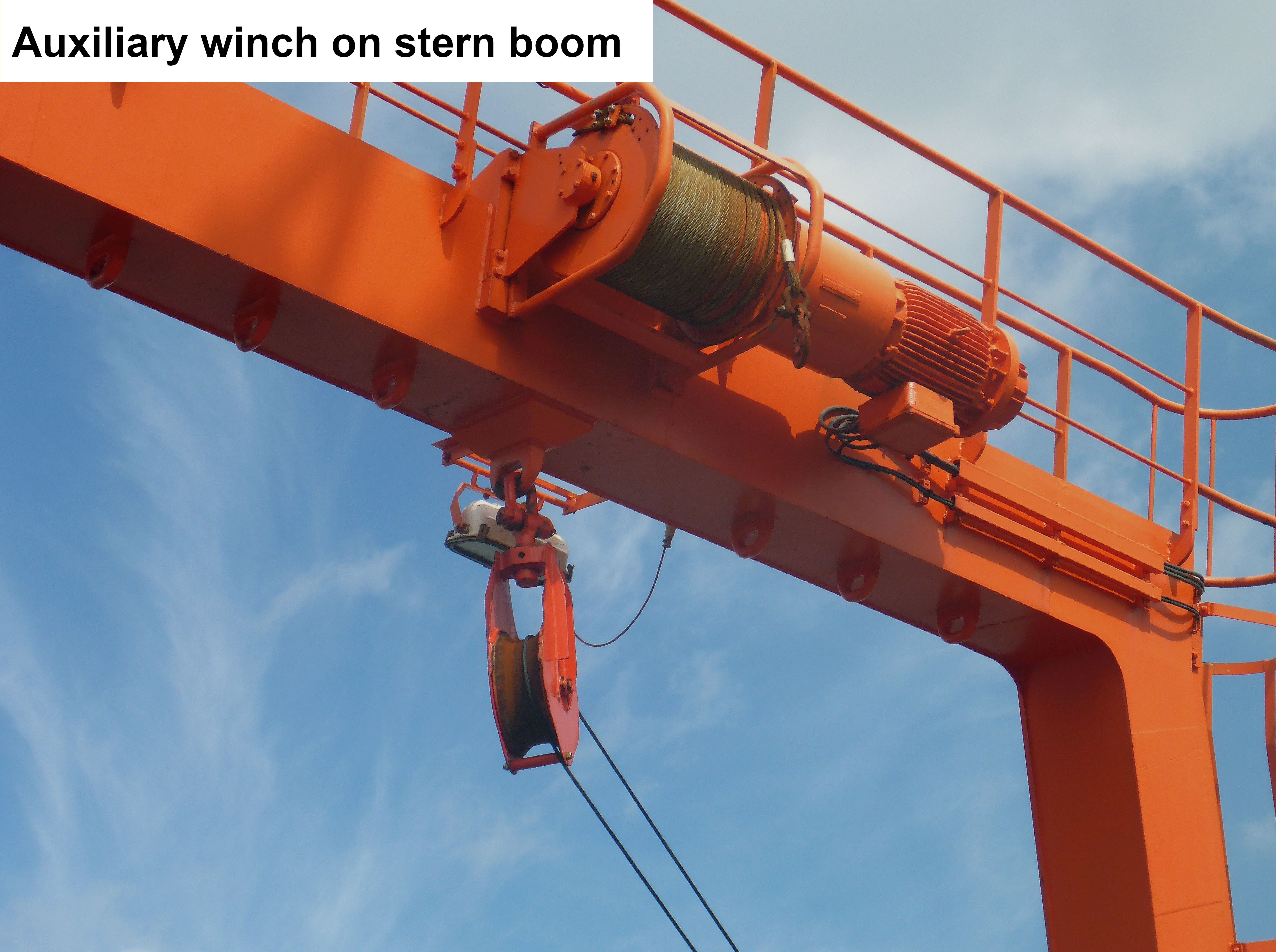
W8 | auxiliary winch on stern boom |
The winches are hydraulic and are powered by a central hydraulic unit. A side boom is installed on the starboard side for keeping winches and cables on the outboard. The side boom operates one of the 4 wires of the drum winches on the starboard side. Astern the cables are lead outboard via the stern boom.
Both, stern boom and side boom has SDL of 3t.
The crane has SWL of 2.5t in full expansion and SWL of 5t in limited expansion until 7m.
4-drum winches
| capacity intermediate rope layer | max. rope speed intermediate rope layer | slip ring transmitter | |
|---|---|---|---|
| W1 | 20 kN | 0..120m/min | yes |
W2 | 30 kN | 0..80m/min | no |
| W3 | 30 kN | 0..80m/min | yes |
| W4 | 20 kN | 0..120m/min | yes |
Trawl line winches
| capacity intermediate rope layer | max. rope speed intermediate rope layer | slip ring transmitter | |
|---|---|---|---|
| W5 and W6 | 40 kN | 0..60m/min | no |
Auxiliary winch on stern boom
| capacity intermediate rope layer | max. rope speed intermediate rope layer | slip ring transmitter | |
|---|---|---|---|
| W8 | 30 kN | 0..40m/min | no |
Wiring
State of October 2019
W1 | 8mm COAX cable, length 2935m, 9.2 Ohm/km, connector SubConn IL-2-F (female) requiring IL-2-M (male) connector on the device side |
W2 | 12mm wire, steel wire SOLIFLEX 32, length 2000m, 98 kN breaking force |
W3 | 11mm COAX/LWL cable, NSW cross section 138350, length 2000m, 70 kN breaking force, connector GISMA BR40 Gr3 |
W4 | 11mm COAX cable, length 2370m, 19 Ohm/km, connector SubConn IL-2-F (female) requiring IL-2-M (male) connector on the device side |
W5 and W6 | 18mm steel wire, length 2400m on each starboard side and portside |
W8 | 16mm galvanised steel wire, length 40m |
Winches W1, W3 and W4 have slip ring collector and W3 additionally fiber optic transmitter for electric supply and data communication. From each winch a cable of type RGU214U leads to the patch field in Mess- und Registrierraum. Connectors of patch field are N-Type sockets with outer thread. An adapter to BNC socket is available. The fiber optic patch field has two plugs of ST type (bayonet socket).
The pins of fiber optic socket GISMA BR40, Gr 3 (GISMA 40.06.3.06.2.00) are:
Pin 1+2 combined for electric power, center Coax
Pin 4+5 combined for electric power, screen Coax
Pin 3 for fiber optic (line 1)
Pin 6 for fiber optic (line 2)
Cables and wires from 4-drum winch can be traced via pulleys to stern boom.
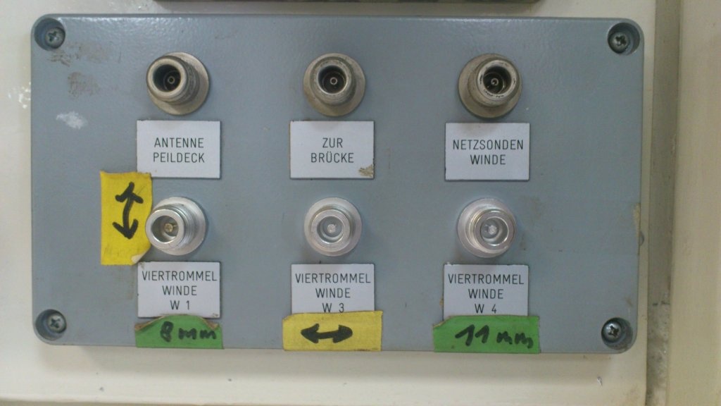
Patch field with N-Type sockets in Mess- und Registrierraum for COAX cables |
Patch field with ST sockets in Mess- und Registrierraum for fibre optic connectors; laboratory side of 11mm cable on winch W3. |
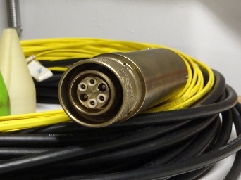
Fibre optic socket GISMA BR40, Gr 3 (GISMA 40.06.3.06.2.00); wet side of 11mm cable on winch W3 |

| Note | ||
|---|---|---|
| ||
The need of the system has to be announced in cruise planning document "Einsatzplanung" prior to the cruise. The mounting of USBL antenna is executed by ships crew, the operation of the system must be executed by experienced scientific staff. GAPS underwater communication is conducted by using various frequencies, interferences with simultaneously operating Echo Sounders are possible. Attention: Submarine cable must be connected and device must be submerged in water before activating GAPS. |
Summary
| Sensorweb integration | ||||
|---|---|---|---|---|
| ||||
The Global Acoustic Positioning System (GAPS) combines an ultra-short baseline (USBL) acoustic positioning system and an inertial navigation system (INS) in the same housing to provide accurate position of any subsea object supplied with a transponder. Operating range is up to 4000m water depth with accuracy 0.2 percent of the distance to the object. The registration angle of 200 degree also enables position registration in shallow water. |
| Sensorweb integration | ||||||||
|---|---|---|---|---|---|---|---|---|
| ||||||||
|
...
| urn | vessel:heincke:gaps |
|---|---|
| contenttype | Images |


Transducer Frequency:
| Metadata (Metadata Plugin) | ||
|---|---|---|
| ||
GAPS: from 22 to 30 kHz; Transponder: 19.5, 20.0, 20.5 or 21 kHz |
Contacts
| Sensorweb integration | ||||||
|---|---|---|---|---|---|---|
| ||||||
|
Components
The system consists of the GAPS antenna itself, mounting for installation at the ships bottom, the Easy Connect Box (ECB) and monitoring software "GAPS MMI - Man Machine Interface". The transponders can be mounted to winch wire or to a submarine vehicle or other submarine object.
GAPS is a bi-directional acoustic positioning system, which communicates between ship (antenna) and one or more transponders. Positions of the transponders are determined relative to the ship or absolute in geographic frame. GAPS must be installed with custom-built mounting and is operated below the ship's hull. It is deployed via the Hydrographenschacht.
Two acoustic transponders (MT832E-R and MT832E-HD-R) are available onboard RV Heincke. The transponders must be mechanically attached to underwater objects or vehicles. The transponders are synchronized to the GAPS and can be operated in transponder-mode (acoustic transmission and receiving) or in responder-mode (electric transmission and acoustic receiving; cables and plugs for responder-mode are not available on board). For transponder MT832E-R exists a winch cable mounting.
The Easy Connect Box (ECB) is a small interface to connect GAPS, external GPS receiver, PC with MMI-software and data management system DShip. It is switched on via the switch at the back of the ECB. The switch on the front is for the GAPS itself.
The GAPS MMI - Man Machine Interface - Software starts the GAPS and tracks the underwater transponders. It is installed on the CTD-PC in the Mess- und Registrierraum.
GAPS is connected to the GPS receiver on-board. Still there is an extra GPS receiver with accessories in case you want to use GAPS somewhere else.
| Sensorweb integration | ||||
|---|---|---|---|---|
| ||||
No subdevices found for this sensor. |
Position
| Sensorweb integration | ||||
|---|---|---|---|---|
| ||||
|
Data logging, storage and archiving
Logged parameters
| Sensorweb integration | ||||||||||||||||||||||||||||||||||||||||||||||||
|---|---|---|---|---|---|---|---|---|---|---|---|---|---|---|---|---|---|---|---|---|---|---|---|---|---|---|---|---|---|---|---|---|---|---|---|---|---|---|---|---|---|---|---|---|---|---|---|---|
| ||||||||||||||||||||||||||||||||||||||||||||||||
|
Central geographical ship's position and time standard
| Metadata (Metadata Plugin) | ||
|---|---|---|
| ||
Time synchronising of the PC with MMI-Software via Windows-Domain-Affiliation. Centering of GPS-antenna position to GAPS and to transponders. |
Rawdata storage on board
| Metadata (Metadata Plugin) | ||
|---|---|---|
| ||
Data storage in DShip system.
|
DShip
| Metadata (Metadata Plugin) | ||
|---|---|---|
| ||
Uncorrected measurement data. |
| Metadata list |
|---|
|| Device name | GAPS ||
|| Parameters| Transponder2; Transponder3; Transponder1; Ship0; Altitude std dev; GAPS.HEHDT.Sentence; GAPS.PIXSE.ATI.datafield01;  GAPS.PIXSE.ATI.datafield04; GAPS.PIXSE.STDH.datafield01; GAPS.PIXSE.STDP.datafield01; Heading \[deg\]; Heading std dev; Latitude std dev; Longitude std dev; Pitch \[deg\]; Pitch std dev; Roll \[deg\]; Roll std dev ||
|| Transponder Parameter| Day; Depth \[m\]; EW; Month; NS; Time; Transponder No SAG; Transponder No SAX; X coordinate \[m\]; Y coordinate \[m\]; Year; Z coordinate \[m\] ||
|| Ship0 Parameter| Day; Depth \[m\]; EW; GAPS.PTSAG.0.Latitude; GAPS.PTSAG.0.Longitude; Month; NS; Time; Transponder_No_SAG;Transponder_No_SAX; X_coordinate \[m\]; Y_coordinate \[m\]; Year; Z_coordinate \[m\] || |
Data archiving on land
| Metadata (Metadata Plugin) | ||
|---|---|---|
| ||
After the cruise the DShip data set can be extracted from https://dms.awi.de.
|
Documentation
...
| urn | vessel:heincke:gaps |
|---|---|
| contenttype | Resources |
...